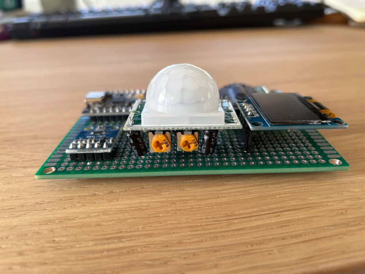
Motion activated smart home display
2 August 2026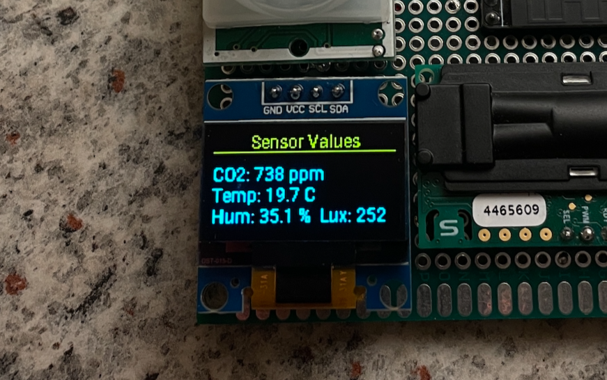
I recently ordered an ESP32 kit with a few sensors including a 1" SSD1306 OLED screen and a PIR (infrared) motion sensor. The extra ESP32 is useful when wanting to experiment but not break any existing projects.
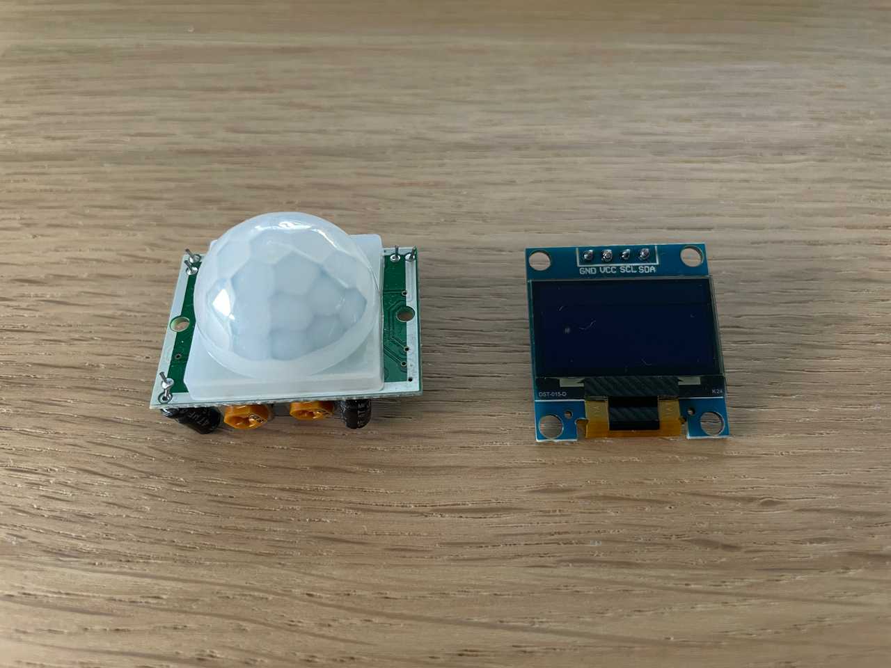
The OLED uses the I2C protocol for communication. The motion sensor uses a regular output pin that's LOW in idle and HIGH when motion is detected. The combination of these two components allow me to display any information (such as CO2, temperature, humidity, illuminance) on a screen that's activated by nearby motion. I only bought a kit because it had exactly the components I wanted but then for a cheaper price with a bunch of extras.
When buying the kit, I decided to buy a modern USB C powered soldering iron. Specifically, the FNIRSI HS-02A. It's a 100W iron that can comfortably be powered by a 65W laptop power supply. It has a little screen and a few buttons that let you adjust temperature and it has an auto-sleep mode that triggers when you lay the iron down. The truly mindboggling thing (to me) is the speed at which it heats up. Literally a few seconds and it's up to 100 °C. That's unimaginable compared to what I was used to; cheap generic soldering stations.
Going back to the project, the goal is twofold:
- Viewing sensor values without a phone.
- Fully self contained and portable (no need for WiFi)so I can take it anywhere.
I first tried connecting the ESP32 to the motion sensor and screen using a breadboard to make sure everything was in working order and most importantly to prove my idea would work.
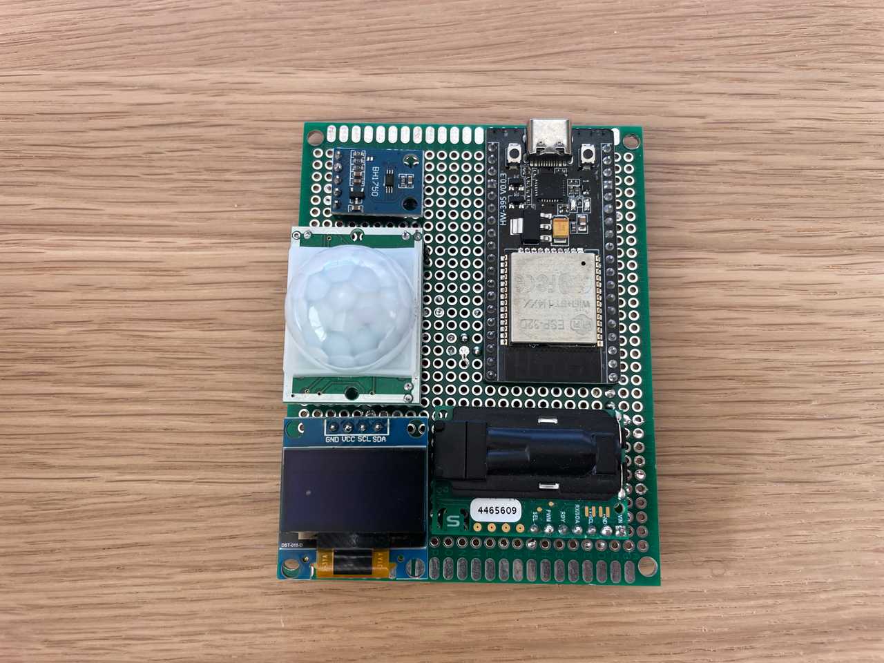
As I have some minor regrets soldering my (previously) only ESP32 directly to perfboard, I wanted to experiment with header pin standoffs that allow removing and placing components without permanently soldering them to a board. The second reason for using standoffs is that the motion sensor doesn't fit directly on the perfboard because of its bulky bottom mounted components.
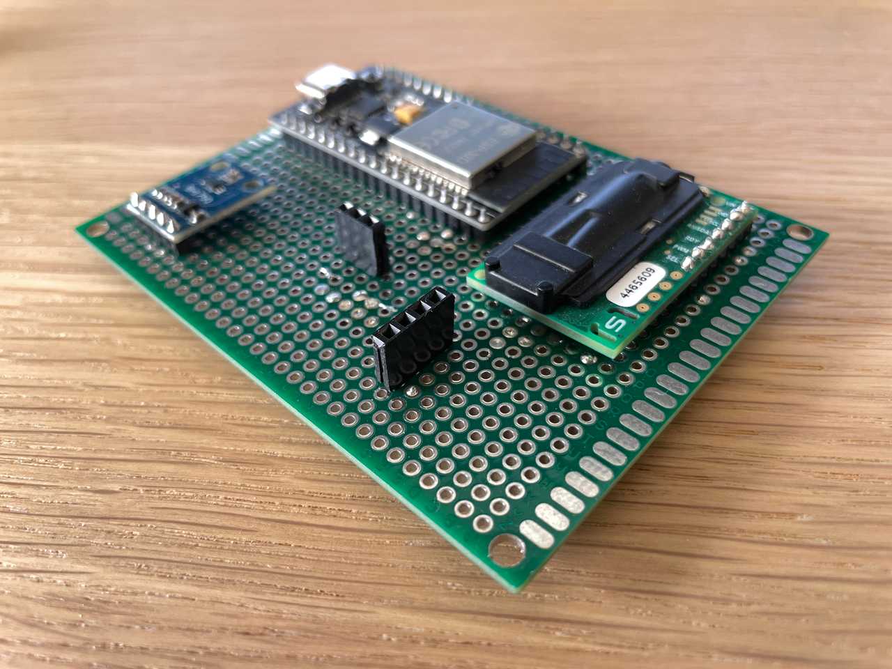
The wiring is a bit of a hot mess, but it works. I'm glad I initially chose a relatively large perfboard as it's getting pretty crowded. I have a few more sensors I'd like to mount in the future. It's going to be tight.
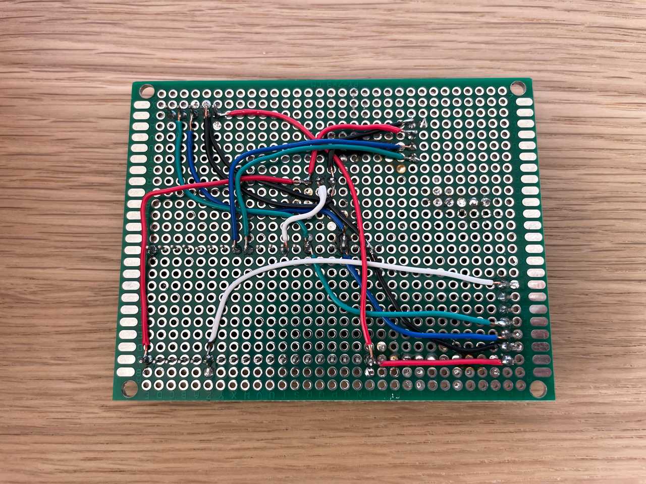
I decided to connect screen to its own I2C pins as I was afraid to break the existing sensor's connections. I wired up both components to 3.3 V initially but discovered the motion sensor produces unreliable results at 3.3 V. Therefore, I hooked them both up to 5 V instead.
Now for the software. This time around, I used the Home Assistant ESPHome Device Builder app which worked like a charm. You simply connect the ESP32 to the machine running Home Assistant. In my case, this is my server. When running Proxmox, give the Home Assistant VM access to the USB port. Then, open the builder app, select the ESP32 device type (I chose 'generic'), name it and you'll be directed to the configuration file editor. From here, create your desired configuration (see below) and click Upload.
# I2C pin definitions
i2c:
  - id: bus_a
    sda: 21
    scl: 22
  - id: bus_b
    sda: 17
    scl: 16

# Motion sensor
binary_sensor:
  - platform: gpio
    pin:
      number: GPIO19
      mode: INPUT
    id: motion_sensor
    name: "Motion"
    device_class: motion
    on_press:
      - lambda: |-
          id(oled_display).turn_on();
    on_release:
      - delay: 30s
      - lambda: |-
          id(oled_display).turn_off();

# CO2, temperature, humidity and light sensors
sensor:
  - platform: scd30
    co2:
      name: "CO2"
      id: co2
      accuracy_decimals: 1
    temperature:
      name: "Temperature"
      id: temperature
      accuracy_decimals: 2
    humidity:
      name: "Humidity"
      id: humidity
      accuracy_decimals: 1
    address: 0x61
    i2c_id: bus_a
    update_interval: 30s
  - platform: bh1750
    name: "Illuminance"
    id: illuminance
    address: 0x23
    i2c_id: bus_a
    update_interval: 60s

# Display
font:
  - file: "gfonts://Roboto"
    id: my_font
    size: 12

display:
  - platform: ssd1306_i2c
    model: "SSD1306 128x64"
    id: oled_display
    address: 0x3C
    i2c_id: bus_b
    update_interval: 30s
    lambda: |-
      it.printf(64, 0, id(my_font), TextAlign::TOP_CENTER, "Sensor Values");
      it.line(0, 14, 128, 14);
      it.printf(0, 20, id(my_font), "CO2: %.0f ppm", id(co2).state);
      it.printf(0, 34, id(my_font), "Temp: %.1f C", id(temperature).state);
      it.printf(0, 48, id(my_font), "Hum: %.1f %%  Lux: %.0f", id(humidity).state, id(illuminance).state);
This works great except for when the motion sensor is too close to your WiFi router. My server is positioned right below a WiFi router, and placing the motion sensor right next to these devices causes erratic and unreliable motion sensor behaviour. Moving the sensor board a few meters away solves this issue.
The motion sensor's sensitivity can be tweaked using the dials on the side of the module using a Phillips screw driver. I adjust the sensitivity on mine all the way to low, which is equivalent to a sensitivity up to 3 meters instead of 7 meters.